Variance evaluation and optimization of the utmost worth of the drag improve charge
To realize the most effective regression evaluation accuracy, energy perform transformation exams had been utilized to (varepsilon_{tf}), (varepsilon_{vf}) and (varepsilon_{pf}). It was discovered that each one three parameters required energy perform transformations. The detailed transformation parameters are proven in Desk 1. After transformation, the parameters (varepsilon_{tf}{prime}), (varepsilon_{vf}{prime}) and (varepsilon_{pf}{prime}) had been obtained.
Variance evaluation was carried out on the parameters (varepsilon_{tf}{prime}), (varepsilon_{vf}{prime}) and (varepsilon_{pf}{prime}) with the outcomes proven in Desk 2. The information point out that the coefficients of dedication R2 for the regression equations of the three parameters are 0.9691, 0.9473 and 0.9684, respectively. This demonstrates that the regression equations for all three parameters have good confidence ranges.
From the importance rating of the components, it may be seen that move velocity (X3) has a extremely vital impression on the drag improve charge (varepsilon_{tf}), viscous drag improve charge (varepsilon_{vf}), and strain drag lower charge (varepsilon_{pf}). Moreover, X22 and X1X2 even have vital results on all three parameters. Since each X22 and X1X2 are associated to the microgap width, this means that the microgap width can also be a key issue affecting the drag-increasing traits. Comparatively talking, the variables associated to microcylinder diameter X1 and X12 are much less vital, suggesting that the microcylinder diameter is a secondary issue affecting the drag-increasing traits. Notably, X22 has a larger significance than X3 in affecting the viscous drag improve charge (varepsilon_{vf}), indicating that the hole to diameter ratio performs an important function in viscous drag. That is associated to the underlying reason behind viscous drag. As proven in Desk 2, viscous drag is the first supply of the elevated drag of the seam plate with a number of microcylinders, therefore the hole to diameter ratio is a vital parameter for drag improve.
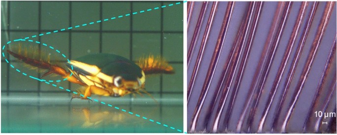
Utilizing the regression mannequin, optimization was carried out for the drag improve charge (varepsilon_{tf}), with the outcomes proven in Desk 3. The information point out that the 9 units of optimization outcomes principally cowl your complete vary of microcylinder diameters. The optimum hole to diameter ratio varies for various microcylinder diameters, however the precise hole dimension is roughly within the vary of twenty-two–35 μm. Contemplating that the diameter of the diving beetle’s swimming hairs is 10–21 μm, and the gaps between the hairs are about 6–23 μm. Subsequently, that is just like the optimization results of group 9. This means that the swimming hairs of diving beetle have glorious hydrodynamic efficiency for rising paddling drag, which is essential for such small-sized organisms. In comparison with steady webbed toes, the gap-distributed swimming hairs decrease vitality loss for the organism, whereas offering higher paddling efficiency than seamless webbed toes. The one downside is the restricted stiffness of the swimming hairs, which can’t stand up to extreme masses. The wonderful efficiency of swimming hair has necessary reference and steering significance for small biomimetic underwater autos. Below the premise of guaranteeing ample paddling efficiency of underwater propulsion parts, their weight ought to be decreased as a lot as potential for the aim of decreasing extra vitality loss through the paddling course of. With restricted battery vitality storage, it’s of nice significance for the endurance of small underwater autos.
Drag variation traits of the multi-microcylinder seam plate
The proportion of viscous drag (r_{v}^{G}) (viscous drag/whole drag × 100%) of the multi-microcylinder seam plate has a sure correlation with the viscous drag proportion (r_{v}^{SC}) of a single microcylinder. When the hole to diameter ratio is comparatively small, the move area on either side of the microcylinders aren’t totally developed because of the constraint of the gaps. Right now, the viscous drag proportion of the seam plate is comparatively small, i.e., (r_{v}^{G}{ . Because the hole to diameter ratio continues to extend, (r_{v}^{G}) regularly converges to (r_{v}^{SC}). When the hole to diameter ratio will increase to the purpose the place the move fields between the microcylinders not intervene with one another, that’s, when every microcylinder is totally impartial, (r_{v}^{G} = r_{v}^{SC}). Subsequently, the vary of ({{r_{v}^{G} } mathord{left/ {vphantom {{r_{v}^{G} } {r_{v}^{SC} }}} proper. kern-0pt} {r_{v}^{SC} }}) (outlined because the ratio of the viscous drag proportion) is (0,1], which is relevant to all multi-microcylinder seam plates. Primarily based on the evaluation within the earlier part, viscous drag is the primary purpose for the elevated drag of the multi-microcylinder seam plate. Therefore, this examine makes use of the dimensionless quantity ({{r_{v}^{G} } mathord{left/ {vphantom {{r_{v}^{G} } {r_{v}^{SC} }}} proper. kern-0pt} {r_{v}^{SC} }}) because the impartial variable to research its intrinsic relationship with the drag traits of the multi-microcylinder seam plate.
As proven in Fig. 2, which illustrates the drag traits curve of the multi-microcylinder seam plate. Determine 2a signifies that the viscous drag proportion (r_{v}^{{G_{max } }}) of the multi-microcylinder seam plate is considerably smaller than the strain drag proportion (r_{p}^{{G_{max } }}), the place, (r_{v}^{{G_{max } }} = {{G_{vf} } mathord{left/ {vphantom {{G_{vf} } {(G_{vf} + G_{pf} )_{max } }}} proper. kern-0pt} {(G_{vf} + G_{pf} )_{max } }}) and (r_{p}^{{G_{max } }} = {{G_{pf} } mathord{left/ {vphantom {{G_{pf} } {(G_{vf} + G_{pf} )_{max } }}} proper. kern-0pt} {(G_{vf} + G_{pf} )_{max } }}). As ({{r_{v}^{G} } mathord{left/ {vphantom {{r_{v}^{G} } {r_{v}^{SC} }}} proper. kern-0pt} {r_{v}^{SC} }}) continues to extend, the viscous drag proportion of the multi-microcylinder seam plate is in a steady rising state, whereas the strain drag proportion is in a sluggish declining state. The expansion charge of the viscous drag proportion is quicker, leading to improved drag-increasing effectiveness of the multi-microcylinder seam plate.

Drag traits curve of the multi-microcylinder seam plate. (a) variation curves of the strain drag (Gpf), viscous drag (Gvf), and drag improve charge (εtf) relative to the seamless plate of the multi-microcylinder seam plate with respect to the ratio of the viscous drag proportion. (Gpf + Gvf)max is the utmost whole drag of the multi-microcylinder seam plate underneath the identical move area circumstances; (b) variation curves of the typical strain drag ((overline{{G_{pf} }})) and common viscous drag ((overline{{G_{vf} }})) on every microcylinder within the multi-microcylinder seam plate with respect to the ratio of the viscous drag proportion. SCpf and SCvf are the strain drag and viscous drag on an remoted microcylinder underneath the corresponding move velocity circumstances, respectively.
When ({{r_{v}^{G} } mathord{left/ {vphantom {{r_{v}^{G} } {r_{v}^{SC} }}} proper. kern-0pt} {r_{v}^{SC} }}) will increase to round 0.9, if the worth of ({{r_{v}^{G} } mathord{left/ {vphantom {{r_{v}^{G} } {r_{v}^{SC} }}} proper. kern-0pt} {r_{v}^{SC} }}) continues to extend, it is going to trigger each the viscous drag proportion (r_{v}^{{G_{max } }}) and the strain drag proportion (r_{p}^{{G_{max } }}) of the multi-microcylinder seam plate to drop quickly, in the end resulting in a swift decline within the drag improve charge of the multi-microcylinder seam plate.
General, the drag improve charges of the three teams of multi-microcylinder seam plates all peak when ({{r_{v}^{G} } mathord{left/ {vphantom {{r_{v}^{G} } {r_{v}^{SC} }}} proper. kern-0pt} {r_{v}^{SC} }}) is between 0.85 and 0.9. Adjustments in microcylinder diameter and move velocity didn’t trigger massive fluctuations within the ({{r_{v}^{G} } mathord{left/ {vphantom {{r_{v}^{G} } {r_{v}^{SC} }}} proper. kern-0pt} {r_{v}^{SC} }}) values comparable to the height drag improve charges. The rise in move velocity solely considerably raised the height drag improve charge of the multi-microcylinder seam plate. In comparison with microcylinder diameter, move velocity has a extra noticeable impression on the drag improve charge. All of those have necessary guiding worth for future engineering functions. Given the identified drag composition of a single microcylinder, i.e., (r_{v}^{SC}) is understood, it’s potential to roughly estimate the drag composition relationship (r_{ve}^{G}) of the multi-microcylinder seam plate when the drag improve charge peaks. Through the use of numerical simulation strategies to acquire the drag composition relationships of the multi-microcylinder seam plate underneath two totally different hole to diameter ratios (i.e., viscous drag proportions (r_{v1}^{G}) and (r_{v2}^{G})), and choosing as massive a spread of hole to diameter ratios as potential to make sure that (r_{v1}^{G}{ , the bisection technique can be utilized to iteratively slim down the hole to diameter ratio vary. This enables for rapidly figuring out the hole to diameter ratio comparable to the optimum drag improve impact.
As proven in Fig. 2b, the typical strain drag and viscous drag performing on a single microcylinder within the multi-microcylinder seam plate proceed to extend till ({{r_{v}^{G} } mathord{left/ {vphantom {{r_{v}^{G} } {r_{v}^{SC} }}} proper. kern-0pt} {r_{v}^{SC} }}) is roughly 0.93. This means that because the hole to diameter ratio will increase, it ends in a rise in each the strain drag and viscous drag performing on a single microcylinder.
The discount in strain drag exhibited by the multi-microcylinder seam plate is attributable to the lower within the variety of microcylinders, which means that the lack of strain drag because of the lack of strong space is larger than the acquire in strain drag ensuing from the enlargement of the gaps. On the similar time, the enlargement of the gaps additionally results in a rise in viscous drag, each of which collectively compensate for the lack of strain drag because of the lack of strong space. Within the preliminary levels, the features in each viscous and strain drags can utterly offset the lack of strain drag, ensuing within the multi-microcylinder seam plate demonstrating drag-increasing mechanical traits.
Because the hole to diameter ratio continues to extend (i.e., the viscous drag proportion ratio ({{r_{v}^{G} } mathord{left/ {vphantom {{r_{v}^{G} } {r_{v}^{SC} }}} proper. kern-0pt} {r_{v}^{SC} }}) continues to extend), the cumulative acquire results of each viscous and strain drags improve the drag-increasing impact of the multi-microcylinder seam plate. When ({{r_{v}^{G} } mathord{left/ {vphantom {{r_{v}^{G} } {r_{v}^{SC} }}} proper. kern-0pt} {r_{v}^{SC} }}) is roughly 0.9, the features from each drags can primarily offset the strain drag loss because of the lack of strong space. At this level, the drag-increasing impact of the multi-microcylinder seam plate reaches its optimum stage.
When ({{r_{v}^{G} } mathord{left/ {vphantom {{r_{v}^{G} } {r_{v}^{SC} }}} proper. kern-0pt} {r_{v}^{SC} }}) continues to extend past this level, though the typical strain drag and viscous drag performing on a single microcylinder proceed to rise, they will not compensate for the strain drag loss because of the discount in strong space. Because of this, the drag-increasing impact of the multi-microcylinder seam plate diminishes and rapidly transitions to a drag-reducing state. In comparison with the strain drag and viscous drag on a single microcylinder, the typical strain drag and viscous drag on every microcylinder within the multi-microcylinder seam plate are smaller within the preliminary levels (with the values of the strain drag proportion curve and the viscous drag proportion curve each being lower than 0). Because of this when there are extra microcylinders, the gaps shall be very small, and the typical strain drag and viscous drag distributed on a single microcylinder are comparatively small.
As ({{r_{v}^{G} } mathord{left/ {vphantom {{r_{v}^{G} } {r_{v}^{SC} }}} proper. kern-0pt} {r_{v}^{SC} }}) continues to extend, the typical strain drag proportion first exceeds 0, which means that the typical strain drag on a single microcylinder turns into larger than the strain drag on an remoted microcylinder, whereas the typical viscous drag stays lower than the viscous drag on an remoted microcylinder. The rationale for that is that viscous drag primarily will depend on the event of the move area throughout the gaps. On the similar time, the uniformly spaced association of the multi-microcylinders creates a sure frontal space, which, in comparison with an remoted microcylinder, ends in a strain drag benefit. This causes the strain drag proportion to be considerably larger than the viscous drag proportion within the preliminary levels.
When ({{r_{v}^{G} } mathord{left/ {vphantom {{r_{v}^{G} } {r_{v}^{SC} }}} proper. kern-0pt} {r_{v}^{SC} }}) exceeds 0.85, the typical viscous drag proportion for the only microcylinder within the multi-microcylinder seam plate regularly turns into larger than 0. At this level, the drag improve charge of the multi-microcylinder seam plate is already nearing its peak. After ({{r_{v}^{G} } mathord{left/ {vphantom {{r_{v}^{G} } {r_{v}^{SC} }}} proper. kern-0pt} {r_{v}^{SC} }}) exceeds 0.9, the typical strain drag and viscous drag on every single microcylinder proceed to extend. Nonetheless, because of the discount within the variety of microcylinders, the entire drag of the multi-microcylinder seam plate begins to lower. Subsequently, the typical strain drag and viscous drag on every single microcylinder begin to lower and finally converge to the strain drag and viscous drag of an remoted microcylinder.
Comparative evaluation of the general strain area and velocity area between the multi-microcylinder seam plate and the seamless plate
To research the traits of every a part of the move area, we chosen the move area information underneath the circumstances of a microcylinder diameter of 40 μm and a move velocity of 0.3 m/s. All move field-related analyses on this paper are primarily based on these circumstances.
As proven in Fig. 3, when the hole to diameter ratio is 0.27 and the viscous drag proportion ratio is 0.53, the strain area of the multi-microcylinder seam plate is just like that of the seamless plate. Each type an “8”-shaped unfavourable strain zone behind the plate, with an elliptical strain focus zone forming behind the “8”-shaped unfavourable strain zone. The high-pressure zone in entrance of the plate can also be principally related. Because the hole to diameter ratio will increase, the “8”-shaped unfavourable strain zone behind the seam plate regularly weakens and shifts additional again, whereas the world of the high-pressure zone close to the entrance of the plate decreases. When the hole to diameter ratio reaches 0.73, the “8”-shaped unfavourable strain zone is not clearly seen.

Stress contours of multi-microcylinder seam plate and seamless plate.
When the hole to diameter ratio reaches 1.11, the “8”-shaped unfavourable strain zone utterly disappears, and an oblong low-pressure zone with comparatively uniform strain kinds close to the rear of the plate. This means that the strain area shaped by the fluid passing via the gaps tends to turn into uniform, and the affect between the gaps is regularly weakening. At this level, the drag improve charge of the multi-microcylinder seam plate has already began to lower. A trapezoidal low unfavourable strain zone kinds additional away from the plate. From the rate contours of the move area, it may be seen {that a} velocity circulation nonetheless kinds at this location, leading to a focus of unfavourable strain on this space.
When the hole to diameter ratios are 1.71 and a pair of.17, the strain values of the unfavourable strain zone behind the plate lower (the lower in strain values refers to a discount within the absolute worth of the unfavourable strain). Though the world of the high-pressure zone close to the entrance of the plate decreases, the world of the secondary high-pressure zone barely farther from the plate will increase, decreasing the drag of the fluid passing via the gaps.
As proven in Fig. 3h, because the hole to diameter ratio will increase, the strain drag of the multi-microcylinder seam plate repeatedly decreases and stays persistently decrease than the strain drag of the seamless plate. Within the preliminary stage, the strain drag decreases slowly. When the viscous drag proportion ratio exceeds 0.85, the strain drag drops quickly, inflicting the drag-increasing impact of the seam plate to start to weaken and finally transition to a drag-reducing state. The common strain drag on a single microcylinder within the multi-microcylinder seam plate continues to extend till the viscous drag proportion ratio reaches 0.9, and it’s typically increased than the strain drag on an remoted microcylinder underneath the identical move area circumstances. It’s because when a number of microcylinders are organized with gaps between them, the outer cross-sectional space shaped between them supplies a sure form drag. This portion of the drag will increase the typical strain drag on every single microcylinder.
Because the viscous drag proportion ratio additional will increase, the quantity of fluid passing via the gaps will increase, resulting in a gradual discount within the form drag of the seam plate, and the typical strain drag on every single microcylinder begins to lower. When the state is reached the place every microcylinder not influences the others (viscous drag proportion ratio equals 1), the typical strain drag on every single microcylinder converges to the strain drag of an remoted microcylinder. Though the typical strain drag on every single microcylinder typically will increase, the strain drag of the seam plate repeatedly decreases. The first purpose for that is that the outer dimensions of the multi-microcylinder seam plate are mounted, and a rise within the hole to diameter ratio ends in a discount within the variety of microcylinders, which in flip reduces the strain drag of the seam plate.
As proven in Fig. 4, when the hole to diameter ratio is 0.27, the rate area of the multi-microcylinder seam plate is just like that of the seamless plate. Two velocity circulations type behind the plate, which is the rationale for the formation of the “8”-shaped unfavourable strain zone. The rate of the fluid behind the plate is comparatively low, whereas the fluid in entrance of the plate accelerates to the edges after being obstructed by the plate. This causes the rate of the fluid on either side behind the plate to be a lot increased than that of the fluid within the center. Because of this, the fluid on either side exerts a backward dragging impact on the fluid within the center, forming a clockwise circulation on the higher half and a counterclockwise circulation on the decrease half.

Velocity contours of multi-microcylinder seam plate and seamless plate.
The 2 circulations converge on the center place behind the plate, rising the move pace within the center, which is reverse in path to the rate of the primary move area. Consequently, two velocity stagnation factors are shaped on the entrance and rear convergence factors of the 2 circulations, and the central areas of the circulations type low-speed areas, that are the “8”-shaped unfavourable strain zones. The 2 circulations create low-speed closed-loop areas that encompass the high-speed fluid within the center. Because the hole to diameter ratio will increase, the low-speed zone near the again of the plate is elongated, indicating that the rate of the fluid passing via the gaps is comparatively low. The low-speed closed-loop area shaped by the circulation zones will get narrower, and the move pace within the central high-speed fluid area decreases. This means that the accelerating impact of the high-speed fluid on either side of the plate on the center fluid weakens, decreasing the pace distinction between them. The 2 circulations turn into weaker, resulting in a lower within the pace of the high-speed fluid on either side behind the plate.
When the hole to diameter ratio reaches 1.11, the rate of the fluid passing via the gaps additional will increase, forming a “parabolic” formed low-speed transition zone close to the again of the plate. Subsequently, the rate additional decreases, forming a narrower low-speed closed-loop area on the rear. The move pace on the heart just isn’t a lot totally different from the pace within the surrounding low-speed area. The depth of the 2 circulations may be very weak, and the move pace of the fluid on either side additionally decreases.
When the hole to diameter ratios are 1.71 and a pair of.17, no velocity circulation zones type behind the seam plate. The move pace within the low-speed area behind the plate continues to extend, indicating a discount within the plate’s blocking impact on the fluid. The move pace of the fluid passing via the gaps additional will increase, and the pace of the fluid on either side of the plate are almost equal to the pace of the primary move area.
As proven in Fig. 4h, earlier than the viscous drag proportion ratio reaches 0.9, the viscous drag of the multi-microcylinder seam plate repeatedly will increase, indicating that the friction between the fluid and the microcylinders is intensifying. Afterward, the viscous drag begins to lower.
Nonetheless, primarily based on the typical viscous drag of a single microcylinder within the seam plate, it’s noticed that the typical viscous drag talked about above repeatedly will increase all through your complete vary of modifications. Within the later levels, it regularly exceeds the viscous drag of an remoted microcylinder underneath the identical move area circumstances, indicating that the friction impact of the fluid throughout the gaps on the microcylinders is repeatedly intensifying. Just like the strain drag of the seam plate, the first purpose for the lower in viscous drag within the later levels is the discount within the variety of microcylinders within the multi-microcylinder seam plate, resulting in a lower within the viscous drag of the entire seam plate. The rate contours reveal that the move area of the multi-microcylinder seam plate is laminar in all circumstances, so the viscous drag of the fluid has a big impression on the entire drag.
Evaluation of the strain area and velocity area contained in the gaps of the multi-microcylinder seam plate
To research the traits of the move area throughout the gaps, move area information from particular places had been extracted. As proven in Fig. 5, the primary focus was on the move area information alongside the road A-A, which is perpendicular to the move path and passes via the middle of the microcylinder, and the road B-B, which is alongside the move path and passes via the middle of the hole (making an attempt greatest to make sure that the hole the place the information extracted from is situated on the heart of the multi-microcylinder seam plate. If the variety of microcylinders is even, the hole is precisely on the heart, and if the variety of microcylinders is odd, the middle of the multi-microcylinder seam plate is a microcylinder. To make sure uniformity, the hole adjoining to the middle microcylinder with an x-coordinate larger than the middle microcylinder was chosen). Moreover, the circumferential tangential velocity of the central microcylinder within the multi-microcylinder seam plate (circumferential line C–C) was additionally extracted, in addition to the strain information on the entrance and rear sides of each the seam and seamless plates (traces D–D and E–E).

Schematic diagram of the situation of every information extraction line. (a) Information extraction line places for the seamless plate; (b) information extraction line places for the seam plate when the variety of microcylinders is even; (c) information extraction line places for the seam plate when the variety of microcylinders is odd.
As proven in Fig. 6, the curves symbolize the variations in velocity and strain alongside the road A-A. When the hole coordinates take integer values, these places correspond to the middle positions of the gaps. Transitioning ahead and backward by 0.5 models provides the coordinates comparable to the perimeters of a single hole, with every integer coordinate representing a niche.

Stream area information of multi-microcylinder seam plate at line A-A. (a) Variation curves of the rate at line A-A; (b) variation curves of the strain at line A-A.
As proven in Fig. 6a, with the continual improve within the hole to diameter ratio, the rate of the fluid throughout the gaps additionally repeatedly will increase, and the rate variations between the gaps lower, indicating that the seam plate’s blocking impact on the fluid is weakening. Earlier than the hole to diameter ratio reaches 0.73, the rate will increase considerably. Nonetheless, after exceeding 0.73, the speed of velocity improve begins to decrease. Because of this within the early levels, the growth of the gaps led to a fast improvement of the inner move area, however additional growth of the gaps didn’t lead to corresponding modifications within the move area. This means that because the gaps proceed to enlarge, their restrictive impact on the fluid weakens. Particularly, when the hole to diameter ratios are 1.71 and a pair of.17, the rate not exhibits a big improve. Nonetheless, in comparison with an remoted microcylinder, the rate throughout the gaps remains to be increased than that of across the remoted microcylinder, indicating that the gaps nonetheless have an accelerating impact on the fluid, though the multi-microcylinder seam plate is already in a drag-reducing state. With the additional improve within the hole to diameter ratio, the rate throughout the gaps will regularly converge to the rate across the remoted microcylinder.
As proven in Fig. 6b, when the hole to diameter ratio is lower than 0.46, the strain contained in the gaps is optimistic, indicating that the fluid inside is in a state of mutual compression. Right now, the multi-microcylinder seam plate displays a sure drag-increasing impact. When the hole to diameter ratio reaches 0.73, unfavourable strain begins to seem throughout the gaps, permitting the fluid to move easily via them. The compressive impact of the gaps weakens, and the multi-microcylinder seam plate achieves its optimum drag-increasing impact. Because the hole to diameter ratio additional will increase, the unfavourable strain contained in the gaps will increase and regularly transitions to the strain round an remoted microcylinder. The restrictive impact of the gaps on the inner fluid additional weakens, and the multi-microcylinder seam plate transitions to a drag-reducing state.
As proven in Fig. 7a, the gaps within the seam plate have a big accelerating impact on the fluid. Because the fluid passes via the gaps, the rate first will increase to a peak worth after which begins to lower. The place that the height velocity seems is usually situated on the cross-sectional line passing via the middle of the microcylinder. Because the hole to diameter ratio will increase, this place shifts backward. This means that the narrowest a part of the hole is not the place the height velocity happens, suggesting that the compressive and accelerating results of the gaps on the fluid are weakening, and the drag-increasing impact of the multi-microcylinder seam plate begins to decrease. After the fluid passes via the gaps, two velocity stagnation factors type behind the multi-microcylinder seam plate. Because the hole to diameter ratio will increase, the positions of those stagnation factors transfer additional again, and the reverse peak velocities additionally lower. When the hole to diameter ratio reaches 1.71, the rate stagnation factors not seem, and the multi-microcylinder seam plate transitions to the drag-reducing state.

Stream area information of multi-microcylinder seam plate at line B-B. (a) Variation curves of the rate at line B-B; (b) variation curves of the strain at line B-B.
As proven in Fig. 7b, when the hole to diameter ratio is comparatively small, the strain distinction throughout the hole is principally just like that of the seamless plate. Because the hole to diameter ratio will increase, the strain in entrance of the hole begins to lower, and the unfavourable strain behind the hole will increase, indicating that the compressive impact of the fluid in entrance of the hole weakens, whereas the suction impact of the fluid behind the hole strengthens. When the hole to diameter ratio reaches 1.11, the strain in entrance of the hole additional decreases, and the unfavourable strain behind it begins to lower. At this level, the drag-increasing impact of the multi-microcylinder seam plate begins to weaken. Because the hole to diameter ratio additional will increase, the strain in entrance of the hole continues to lower, and the unfavourable strain behind the hole regularly converges to the strain behind the seamless plate. The multi-microcylinder seam plate not displays a drag-increasing impact.
As proven in Fig. 8, the circumferential tangential velocity of the central microcylinder within the multi-microcylinder seam plate is depicted. The tangential velocity is outlined as unfavourable within the clockwise path and optimistic within the counterclockwise path. When the hole to diameter ratio is small, the tangential velocity across the circumference reaches its most unfavourable worth on the 90° place and its most optimistic worth on the 270° place, with each positions being on the narrowest a part of the hole. Because the hole to diameter ratio will increase, these positions regularly shift in direction of 60° and 300°. In response to the angular definition within the determine, these two positions are symmetrical to one another and repeatedly transfer ahead, regularly converging to the positions the place the utmost tangential velocities (unfavourable and optimistic) of an remoted microcylinder seem. The distinction from the remoted microcylinder’s tangential velocity regularly diminishes.

Circumferential tangential velocity of the central microcylinder of the multi-microcylinder seam plate.
Within the preliminary levels, the tangential velocity across the central microcylinder doesn’t change in optimistic and unfavourable values close to 180° place. When the hole to diameter ratio reaches 1.71, modifications in optimistic and unfavourable values of the tangential velocity begin to seem across the 180° place for the central microcylinder. This means that fluid circulations have already been shaped across the 150°–180° and 180°–210° areas of the central microcylinder, that’s, slight velocity separations have occurred, leading to modifications in optimistic and unfavourable values of the tangential velocity. At this level, the multi-microcylinder seam plate is in a drag-reducing state.
As proven in Fig. 9, the strain curves of the entrance and rear surfaces of the multi-microcylinder seam plate and the seamless plate are displayed (strain information on the traces D–D and E–E). The determine exhibits that when the hole to diameter ratio is small, the strain of the entrance floor of the multi-microcylinder seam plate fluctuates across the strain curve of the seamless plate’s entrance floor. Because the hole to diameter ratio will increase, the strain fluctuations of the entrance floor of the multi-microcylinder seam plate turn into extra pronounced, with the strain rising on the microcylinders and reducing on the gaps. The strain lower on the gaps is extra vital, indicating that extra fluid passes via the gaps, the impression on the microcylinders strengthens, and the blocking impact of the gaps on the fluid weakens, decreasing the conversion of fluid kinetic vitality to strain.

Stress curves of the entrance and rear surfaces of the multi-microcylinder seam plate and seamless plate.
Because the hole to diameter ratio additional will increase, the strain loss on the gaps turns into extreme, resulting in a drag discount phenomenon within the multi-microcylinder seam plate. The strain of the rear floor of the multi-microcylinder seam plate is usually decrease than that of the seamless plate, exhibiting as unfavourable strain. This means that the unfavourable strain of the rear floor can also be a key think about rising drag. Within the early levels of accelerating the hole to diameter ratio, this unfavourable strain worth repeatedly will increase, and the strain fluctuations between the gaps and microcylinders additionally improve, bettering the drag-increasing impact of the multi-microcylinder seam plate. Because the hole to diameter ratio additional will increase, the unfavourable strain on the gaps decreases considerably, whereas the unfavourable strain on the microcylinders doesn’t change a lot. The strain lack of the entrance and rear surfaces on the gaps results in a extreme lack of drag in your complete multi-microcylinder seam plate. Consequently, the entire drag turns into lower than that of the seamless plate, leading to a drag-reducing phenomenon.